Illustration of a computer with digital network icons, highlighting IT infrastructure and hardware reliability, relevant to the Jacksonville computer network issue.

Jacksonville Computer Network Issue: A Comprehensive Overview of the September 2024 Incident

Illustration of a computer with digital network icons, highlighting IT infrastructure and hardware reliability, relevant to the Jacksonville computer network issue.

In September 2024, the City of Jacksonville faced significant computer network issues that disrupted various municipal services. This incident, known as the Jacksonville computer network issue, impacted access to essential city websites and services, causing concern among residents and stakeholders. This article provides an in-depth analysis of the events, their impact on municipal operations, and the measures taken to resolve the situation.

Background of the Jacksonville Computer Network Issue

The network disruptions began on September 11, 2024, when the City of Jacksonville reported intermittent problems affecting its IT infrastructure. Key websites such as jacksonville.gov and jaxready.com became inaccessible, and services like 630-CITY and city mobile apps experienced outages. Initial reports attributed these disruptions to IT infrastructure configuration issues, with assurances that there was no indication of a cyber-attack or security breach.

Timeline of Events

September 11, 2024: Onset of Network Problems

  • Intermittent Network Issues: The city experienced intermittent network problems affecting multiple services.
  • Affected Services: Access to city websites and mobile apps was disrupted.
  • Initial Response: The city’s IT department began investigating the root cause, focusing on configuration issues within the IT infrastructure.

September 13, 2024: Identification of Hardware Failure

  • Root Cause Identified: The city announced that a hardware failure was the primary cause of the network issues.
  • Technical Collaboration: The technical team, along with key vendor partners, worked diligently to troubleshoot and resolve the issue.
  • Restoration of Services: Most city services were restored, including those of the Jacksonville Fire and Rescue Department (JFRD), the Tax Collector, and the 4th Judicial Circuit Court.

Impact on Municipal Services

Disruption of Websites and Online Services

The network issues significantly impacted the accessibility of essential online resources:

  • City WebsitesJacksonville.gov and jaxready.com were intermittently unavailable.
  • Mobile Apps: City mobile applications faced connectivity problems.
  • Communication Channels: Services like 630-CITY, which residents use for inquiries and assistance, were affected.

Affected Departments and Services

Jacksonville Fire and Rescue Department (JFRD)

  • Service Restoration: JFRD services were among the first to be restored, ensuring emergency services remained operational.

Tax Collector Services

  • Operational Status: Tax collection services experienced brief interruptions but were quickly brought back online.

4th Judicial Circuit Court

  • Court Proceedings: Court operations faced minimal disruptions, with efforts made to maintain the judicial schedule.

Public Defender’s Office

  • Ongoing Issues: Despite the network being operational, the Public Defender’s Office continued to experience some external service impacts.

Response and Troubleshooting Efforts

Technical Team and Vendor Partners

  • Collaborative Effort: The city’s technical team collaborated with key vendor partners to identify and resolve the hardware failure.
  • Troubleshooting: Intensive troubleshooting sessions were conducted to restore network functionality.

Involvement of FBI and Homeland Security

  • Federal Support: The FBI and Homeland Security provided support during the incident.
  • Security Assurance: Their involvement helped ensure that there was no cyber-attack or security breach contributing to the network issues.

Emergency Operations Center (EOC) Activation

  • City Leadership Meetings: City leaders convened at the Emergency Operations Center to address the ongoing challenges.
  • Virtual EOC Meetings: Plans were made for virtual meetings over the weekend to monitor and resolve any persisting problems.

Public Communication and Transparency

Official Statements from the City

  • Regular Updates: The city provided regular updates to keep residents informed about the situation.
  • Transparency: Officials maintained transparency about the root cause and the steps being taken to resolve the issue.

Assurance of No Cyber-Attack or Security Breach

  • Public Reassurance: The city repeatedly assured the public that there was no evidence of a cyber-attack or security breach.
  • Focus on Resolution: Emphasis was placed on resolving the hardware failure and restoring full functionality.

Restoration of Services

Steps Taken to Resolve the Hardware Failure

  • Hardware Replacement: Faulty hardware components were identified and replaced.
  • System Testing: Rigorous testing was conducted to ensure stability before bringing services back online.

Restoration of Most Services

  • Service Resumption: Most municipal services resumed normal operations shortly after the issue was resolved.
  • Continued Monitoring: The technical team continued to monitor the network to prevent future disruptions.

Ongoing Issues and Resolutions

  • Public Defender’s Office: Efforts were ongoing to fully restore all external services for the Public Defender’s Office.
  • Long-Term Solutions: Plans were made to implement long-term solutions to prevent similar hardware failures.

Public Interest and Online Searches

Google Trends Data

  • Surge in Searches: There was a significant increase in online searches related to the Jacksonville computer network issue.
  • Trending Topic: “Jacksonville” became a trending search topic in the United States during this period.

Public’s Search Behavior and Information Needs

  • Information Seeking: Residents searched for updates on service outages, restoration timelines, and official communications.
  • Concern Over Security: Searches also reflected concerns about potential cyber-attacks and the involvement of federal agencies.

Lessons Learned and Future Preventive Measures

Importance of IT Infrastructure Maintenance

  • Regular Upgrades: The incident highlighted the need for regular maintenance and upgrades of IT infrastructure.
  • Hardware Monitoring: Implementing advanced monitoring tools to detect hardware issues before they cause disruptions.

Emergency Preparedness and Response

  • Crisis Management: The activation of the EOC demonstrated the city’s ability to respond to emergencies effectively.
  • Communication Protocols: Establishing clear communication protocols to keep the public informed during crises.

Collaboration with Federal Agencies

  • Federal Partnerships: The support from the FBI and Homeland Security underscored the importance of collaboration.
  • Security Enhancements: Working with federal agencies to enhance cybersecurity measures.

Additional Resources

Conclusion

The Jacksonville computer network issue of September 2024 was a significant event that tested the resilience of the city’s IT infrastructure and emergency response capabilities. Through swift action, collaboration with vendor partners and federal agencies, and transparent communication with the public, the city managed to resolve the hardware failure and restore essential services. As of November 27, 2024, there have been no further reports of network issues in Jacksonville, indicating that the measures taken were effective. The incident serves as a valuable lesson in the importance of proactive IT maintenance and the need for robust emergency response strategies.

127.0.0.1 written in bold black text on a clean, light-colored background, representing the loopback IP address used for local network communication.

Understanding 127.0.0.1:49342: A Comprehensive Guide from Basics to Advanced

127.0.0.1 written in bold black text on a clean, light-colored background, representing the loopback IP address used for local network communication.
An example of the loopback IP address 127.0.0.1 commonly used for local network communication.

If you’ve ever monitored network activity or delved into system configurations, you might have encountered the address 127.0.0.1:49342. This combination of an IP address and a port number can be perplexing, especially if you’re unsure what it signifies or why it’s appearing on your system. This comprehensive guide will explore 127.0.0.1:49342 in depth, covering everything from basic concepts to advanced applications. We’ll delve into what this address means, why it appears, and how it impacts your system’s security and functionality.


What is 127.0.0.1?

Before we dive into the specifics of 127.0.0.1:49342, it’s crucial to understand the fundamentals of what 127.0.0.1 represents in networking.

The Loopback Address Explained

  • 127.0.0.1 is known as the loopback address in IPv4 networking.
  • It is a special IP address that points back to the local machine.
  • When you use 127.0.0.1, you’re essentially communicating with your own computer.

The loopback address is part of the larger 127.0.0.0/8 network range, which spans from 127.0.0.0 to 127.255.255.255. However, 127.0.0.1 is the most commonly used address within this range.

Importance of the Loopback Address

  • Testing and Development: Developers use the loopback address to test network applications locally without the need for external network connections.
  • Network Diagnostics: Pinging 127.0.0.1 checks if the network stack of your operating system is functioning correctly.
  • Isolation: It allows applications to communicate within the same machine securely, without exposing data to external networks.

Understanding the loopback address is fundamental for grasping how local network communication works, especially when combined with specific port numbers like 49342.

Understanding Port Numbers

In networking, IP addresses identify devices, while port numbers identify specific services or applications running on those devices.

What is Port 49342?

  • Port 49342 is a numerical identifier for a specific process or service on a device.
  • Ports range from 0 to 65535, divided into well-known ports, registered ports, and dynamic/private ports.
  • Port 49342 falls into the dynamic/private port range (49152–65535).

Dynamic and Private Ports

  • Dynamic/Private Ports: These are used for temporary or private purposes, often assigned dynamically by the operating system.
  • Ephemeral Ports: Another term for dynamic ports, typically used for client-side communications in TCP/IP networking.

When an application initiates a connection to a server, the client uses an ephemeral port like 49342 for the duration of the session.

Common Reasons for 127.0.0.1:49342 Activity

Seeing activity on 127.0.0.1:49342 is generally normal, but understanding why it’s occurring can help in system administration and security.

Localhost Testing and Development

  • Web Development: Developers may run local servers bound to 127.0.0.1:49342 to test web applications.
  • API Testing: Local APIs might use dynamic ports for testing endpoints without external interference.

Using 127.0.0.1 ensures that the application is accessible only from the local machine, enhancing security during development.

Background Services and Applications

  • Database Services: Local databases like MySQL or PostgreSQL may use dynamic ports for internal processes.
  • Microservices Architecture: Applications using microservices might communicate over localhost using dynamic ports.
  • Custom Applications: Software that requires inter-process communication might bind to 127.0.0.1:49342.

Security Scans and Audits

  • Network Monitoring Tools: Applications like Wireshark or Netstat might reveal connections to 127.0.0.1:49342.
  • Security Audits: Automated scans may flag unknown ports for further investigation.

Understanding which services are using this port can help in identifying potential security risks.

Security Implications

While activity on 127.0.0.1:49342 is generally safe, there are scenarios where it could pose security concerns.

Is 127.0.0.1:49342 Safe?

  • Local Traffic: Since 127.0.0.1 refers to the local machine, traffic doesn’t leave your computer.
  • Controlled Environment: Applications using this address and port are typically under your control.

Potential Risks and Vulnerabilities

  • Malware Activity: Malicious software might use localhost and dynamic ports to hide its communication.
  • Unauthorized Access: If an unauthorized application is using port 49342, it could pose a security threat.
  • Port Conflicts: Multiple applications trying to use the same port can cause system instability.

It’s essential to regularly monitor port usage to ensure that only trusted applications are communicating over these ports.

Monitoring and Managing Port Usage

Keeping track of active ports and the applications using them is a critical aspect of system administration.

How to Check Active Ports

On Windows

  1. Open Command Prompt: Press Win + R, type cmd, and hit Enter.
  2. Run Netstat Command: Type netstat -ano | findstr :49342 and press Enter.
  3. Review Output: The command displays active connections using port 49342.

On macOS/Linux

  1. Open Terminal: Use Spotlight or your preferred method to open Terminal.
  2. Run Lsof Command: Type lsof -i :49342 and press Enter.
  3. Analyze Results: The output shows which process is using port 49342.

Identifying Processes Using Port 49342

  • Process ID (PID): Both commands provide the PID of the process.
  • Task Manager/Activity Monitor: Use these tools to cross-reference the PID and identify the application.
  • Third-Party Tools: Applications like Process Explorer can provide more detailed information.

Once you’ve identified the application, you can decide whether it’s necessary or if it should be terminated.

Advanced Troubleshooting

For more complex scenarios, advanced troubleshooting techniques may be required.

Using Network Monitoring Tools

  • Wireshark: A powerful tool for analyzing network traffic at a granular level.
  • NetMon: Microsoft’s Network Monitor can help in diagnosing network issues.

These tools can capture and analyze packets to and from 127.0.0.1:49342, helping you understand what’s happening under the hood.

Analyzing Network Traffic

  • Protocol Analysis: Determine what protocols are being used over the connection.
  • Data Inspection: Look at the actual data being transmitted to ensure it’s legitimate.
  • Session Tracking: Monitor the duration and frequency of connections to port 49342.

Advanced analysis can help identify unusual patterns that may indicate security issues.

Best Practices for System Security

Implementing best practices can help prevent unauthorized use of ports and enhance overall system security.

Regular System Monitoring

  • Scheduled Scans: Regularly scan your system for open ports and active connections.
  • Audit Logs: Keep logs of network activity for future reference.
  • Alerts: Set up alerts for when new ports are opened.

Firewall Configuration

  • Inbound and Outbound Rules: Configure your firewall to restrict or allow traffic on specific ports.
  • Application Control: Use the firewall to control which applications can access the network.
  • Port Blocking: If port 49342 is not needed, consider blocking it.

Software Updates and Patch Management

  • Regular Updates: Keep your operating system and applications up-to-date to patch vulnerabilities.
  • Security Patches: Prioritize updates that address security issues.
  • Trusted Sources: Only download software from reputable sources to avoid malware.

Staying proactive with updates reduces the risk of exploitation through known vulnerabilities.

Frequently Asked Questions

Why is an application using 127.0.0.1:49342 without my knowledge?

Some applications run background services that use dynamic ports for inter-process communication. If you’re unsure about a service, research the application or consult system logs.

Can I change the port number from 49342 to something else?

Yes, if the application allows configuration of the port number. Check the application’s settings or documentation.

Is it normal to have multiple connections to 127.0.0.1 with different ports?

Yes, especially if you have multiple applications or services running that communicate locally. Each connection may use a different dynamic port.

How do I know if a connection to 127.0.0.1:49342 is malicious?

Monitor the associated process and research it. If it’s an unfamiliar or suspicious application, consider terminating it and running a malware scan.

Should I block port 49342 on my firewall?

If you’re not using any applications that require this port, you can block it. However, ensure that doing so doesn’t disrupt necessary services.

Conclusion

The address 127.0.0.1:49342 represents a local connection on your machine using a dynamic port. Understanding this concept is essential for network troubleshooting, development, and security. While activity on this address and port is generally safe and normal, being vigilant about monitoring and managing port usage is crucial.

By grasping both the basics and advanced aspects of 127.0.0.1:49342, you empower yourself to maintain a secure and efficient computing environment. Whether you’re a developer testing applications or a system administrator ensuring network integrity, this knowledge is invaluable.


In today’s interconnected world, awareness of your system’s network activity is more important than ever. Regular monitoring, adherence to best practices, and proactive security measures will help you navigate the complexities of network management with confidence.

Application Layer

Application Layer of OSI Model | Computer Networks

Application Layer

The application layer, in the context of computer networking, refers to the topmost layer of the OSI (Open Systems Interconnection) model or the TCP/IP (Transmission Control Protocol/Internet Protocol) model. It serves as the interface between network-aware applications and the underlying network infrastructure.

This layer also makes a request to its bottom layer, which is presentation layer for receiving various types of information from it. The Application Layer interface directly interacts with application and provides common web application services. This layer is basically highest level of open system, which provides services directly for application process.

The application layer provides services and protocols that enable communication between different software applications running on devices connected to a network. It abstracts the complexities of lower-level networking protocols and facilitates high-level communication, data exchange, and interaction between end-users or applications.

Key responsibilities of the application layer include:

  • Data Representation and Encryption:
    • Ensuring that data is presented in a format that is understandable by the receiving application. This may involve data compression, encryption, and formatting.
  • Communication Services:
    • Providing various communication services such as email, file transfer, remote login, and web browsing. Protocols like SMTP (Simple Mail Transfer Protocol), FTP (File Transfer Protocol), SSH (Secure Shell), and HTTP (Hypertext Transfer Protocol) operate at this layer.
  • Application Layer Protocols:
    • Supporting application layer protocols that define the rules and conventions for communication between applications. Examples include HTTP, SMTP, POP3 (Post Office Protocol version 3), IMAP (Internet Message Access Protocol), DNS (Domain Name System), and SNMP (Simple Network Management Protocol).
  • Client-Server Communication:
    • Facilitating communication between clients and servers. In client-server architectures, the application layer on the client side interacts with the application layer on the server side to request and receive services.
  • User Authentication and Authorization:
    • Providing mechanisms for user authentication and authorization. This may involve login procedures, password authentication, and access control.
  • Error Handling and Recovery:
    • Handling errors that occur during data transmission and implementing mechanisms for error recovery and retransmission if necessary.
  • Application Interfaces:
    • Providing interfaces and APIs (Application Programming Interfaces) that allow applications to access network services and communicate with other applications effectively.

Application Layer Protocols

The application layer of the OSI model encompasses a wide range of protocols and services that enable communication between networked applications. Here are some of the most common application layer protocols:

  • Hypertext Transfer Protocol (HTTP):
    • HTTP is used for transmitting hypermedia documents, such as HTML files, over the World Wide Web. It defines how web browsers and web servers communicate to request and deliver web pages and other resources.
  • Simple Mail Transfer Protocol (SMTP):
    • SMTP is used for sending and receiving email messages between mail servers. It handles the transfer of email messages from the sender’s mail server to the recipient’s mail server.
  • Post Office Protocol version 3 (POP3):
    • POP3 is an email retrieval protocol used by email clients to retrieve messages from a mail server. It allows users to download emails from the server to their local device for reading and storage.
  • Internet Message Access Protocol (IMAP):
    • IMAP is another email retrieval protocol that allows users to access and manage email messages stored on a remote mail server. Unlike POP3, IMAP keeps messages on the server and provides more advanced features for organizing and searching emails.
  • File Transfer Protocol (FTP):
    • FTP is used for transferring files between a client and a server over a network. It provides commands for uploading, downloading, renaming, and deleting files on a remote server.
  • Simple Network Management Protocol (SNMP):
    • SNMP is used for managing and monitoring network devices, such as routers, switches, and servers. It allows network administrators to collect and analyze information about device performance, status, and configuration.
  • Domain Name System (DNS):
    • DNS is used for translating domain names (e.g., www.example.com) into IP addresses (e.g., 192.0.2.1) and vice versa. It enables users to access websites and other network resources using human-readable domain names.
  • Dynamic Host Configuration Protocol (DHCP):
    • DHCP is used for dynamically assigning IP addresses and other network configuration parameters to devices on a network. It automates the process of network configuration, making it easier to manage large networks.
  • Secure Shell (SSH):
    • SSH is a secure network protocol used for remote login and command execution on a remote device. It provides encrypted communication between the client and server, protecting sensitive information from eavesdropping and tampering.
  • Remote Desktop Protocol (RDP):
    • RDP is used for accessing and controlling a remote desktop or graphical user interface (GUI) over a network. It allows users to remotely connect to and interact with a desktop environment on another computer.

Working of Application Layer

The application layer in a computer network works by facilitating communication between different software applications running on devices connected to the network. Here’s a general overview of how it works:

  • Interface with User Applications:
    • The application layer provides an interface for user applications to access network services. Applications interact with the application layer through APIs (Application Programming Interfaces) or protocols specifically designed for communication at this layer.
  • Protocol Selection and Configuration:
    • When an application needs to communicate with another application over the network, the application layer selects the appropriate communication protocol based on the requirements of the application and the network environment. For example, if a web browser wants to retrieve a web page from a server, it may use the HTTP (Hypertext Transfer Protocol) protocol.
  • Data Preparation and Formatting:
    • Before data is transmitted over the network, the application layer prepares and formats the data according to the requirements of the chosen protocol. This may involve tasks such as data compression, encryption, and encapsulation into packets suitable for transmission.
  • Initiating Communication:
    • Once the data is ready, the application layer initiates communication with the corresponding application on another device. This involves establishing a connection, if necessary, and sending the data packets over the network.
  • Protocol Handling and Processing:
    • As data packets are transmitted over the network, the application layer on the receiving end receives and processes them according to the chosen protocol. It performs tasks such as packet disassembly, data decryption, and error checking to ensure the integrity and correctness of the received data.
  • Delivering Data to User Applications:
    • Once the data packets are processed, the application layer delivers the data to the appropriate user application running on the receiving device. This enables the application to interpret and utilize the received data for further processing or display to the user.
  • Handling User Authentication and Authorization:
    • In cases where user authentication and authorization are required, the application layer facilitates these processes by interacting with authentication servers and verifying user credentials before allowing access to network resources or services.
  • Error Handling and Recovery:
    • Throughout the communication process, the application layer handles errors and ensures reliable data transmission. This may involve detecting and retransmitting lost or corrupted data packets, as well as implementing error correction mechanisms to maintain data integrity.

Services of Application Layer

The application layer in computer networks provides a wide range of services to support communication between networked devices and enable the exchange of data between applications. Some of the key services offered by the application layer include:

  • Email Services:
    • The application layer supports email services, allowing users to send, receive, and manage electronic messages over the network. Protocols such as SMTP (Simple Mail Transfer Protocol), POP3 (Post Office Protocol version 3), and IMAP (Internet Message Access Protocol) are commonly used for email communication.
  • File Transfer Services:
    • Application layer protocols such as FTP (File Transfer Protocol) and SFTP (SSH File Transfer Protocol) facilitate the transfer of files between devices connected to the network. These services enable users to upload, download, and manage files stored on remote servers.
  • Web Services:
    • The application layer supports web services, enabling users to access and interact with websites and web applications over the internet. Protocols such as HTTP (Hypertext Transfer Protocol) and HTTPS (HTTP Secure) are used for communication between web clients (e.g., web browsers) and web servers.
  • Remote Access Services:
    • Application layer protocols such as SSH (Secure Shell) and Telnet enable remote access to networked devices and systems. These services allow users to log in to remote servers and access command-line interfaces or graphical user interfaces for system administration and management.
  • Domain Name Services (DNS):
    • The application layer includes DNS services, which translate domain names (e.g., www.example.com) into IP addresses (e.g., 192.0.2.1) and vice versa. DNS resolution is essential for identifying and accessing network resources by their domain names.
  • Directory Services:
    • Application layer directory services, such as LDAP (Lightweight Directory Access Protocol), provide a centralized directory of network resources and user information. These services support authentication, authorization, and user management across distributed network environments.
  • Network Management Services:
    • The application layer supports network management services, allowing administrators to monitor, configure, and troubleshoot network devices and resources. Protocols such as SNMP (Simple Network Management Protocol) enable the collection and exchange of network management information.
  • Real-Time Communication Services:
    • Application layer protocols such as SIP (Session Initiation Protocol) and RTP (Real-time Transport Protocol) support real-time communication services, including voice and video calls, conferencing, and multimedia streaming over IP networks.
  • Database Services:
    • The application layer includes database services, enabling applications to access and manipulate databases stored on remote servers. Protocols such as ODBC (Open Database Connectivity) and JDBC (Java Database Connectivity) facilitate database connectivity and query execution.
  • Collaboration Services:
    • The application layer supports collaboration services, enabling users to work together on shared documents, projects, and tasks. Examples include collaborative document editing platforms, project management tools, and virtual whiteboards.
What is the application layer in computer networks?

The application layer is the topmost layer of the OSI (Open Systems Interconnection) model and the TCP/IP (Transmission Control Protocol/Internet Protocol) model. It provides network services directly to end-users or applications running on those end-user devices.

What are some common protocols used in the application layer?

Some common protocols used in the application layer include HTTP (Hypertext Transfer Protocol), SMTP (Simple Mail Transfer Protocol), FTP (File Transfer Protocol), DNS (Domain Name System), DHCP (Dynamic Host Configuration Protocol), and SNMP (Simple Network Management Protocol).

What is the role of the application layer in networking?

The application layer facilitates communication between different applications or processes running on separate networked devices. It provides services such as email, file transfer, remote login, web browsing, and network management. It also handles data representation, encryption, user authentication, and error handling.

What is the difference between HTTP and HTTPS?

HTTP (Hypertext Transfer Protocol) is a protocol used for transmitting hypermedia documents, such as web pages, over the World Wide Web. HTTPS (HTTP Secure) is a secure version of HTTP that uses encryption to protect data transmitted between the client and server, ensuring confidentiality and integrity.
OSI Model of Computer Network

OSI Model of Computer Network

OSI Model of Computer Network

What is OSI Model

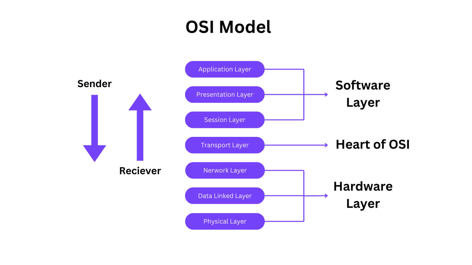
The OSI (Open Systems Interconnection) model is a conceptual framework used to understand and describe how different networking protocols and technologies interact with each other. It divides network communication into seven distinct layers, each responsible for specific functions.

  • OSI consists of seven layers, and each layer performs a particular network function.
  • OSI model was developed by the International Organization for Standardization (ISO) in 1984, and it is now considered as an architectural model for the inter-computer communications.
  • OSI model divides the whole task into seven smaller and manageable tasks. Each layer is assigned a particular task.
  • Each layer is self-contained, so that task assigned to each layer can be performed independently.

7 Layers of OSI Model

Physical Layer

The physical layer is responsible for transmitting raw data bits over a physical medium, defining the characteristics of the physical connection, and converting digital data into signals suitable for transmission over the medium.

Functions:

  • Concerned with transmitting raw data bits over a physical medium.
  • Defines the characteristics of the physical connection, including voltage levels, cable types, and data rates.
  • Converts digital data into signals suitable for transmission over the physical medium.
  • Manages physical connections and controls the transmission of data.

Data Link Layer

The data link layer provides error-free transfer of data frames between adjacent nodes over a physical link, handles framing, error detection, and correction, and controls access to the physical medium.

  • Framing:
    • The Data Link Layer encapsulates network layer packets into data frames for transmission over the physical medium. It delineates where one frame of data ends and the next one begins, allowing devices to identify and extract individual frames.
  • Error Detection and Correction:
    • This layer is responsible for detecting errors that may occur during transmission, typically through techniques like checksums or CRC (Cyclic Redundancy Check). If errors are detected, the Data Link Layer may attempt to correct them using mechanisms such as automatic repeat request (ARQ) or forward error correction (FEC).
  • Flow Control:
    • The Data Link Layer manages the flow of data between devices to ensure that the sender does not overwhelm the receiver with data. It implements flow control mechanisms to regulate the rate at which data is transmitted, preventing buffer overflows and data loss.
  • Access Control:
    • In shared media networks, such as Ethernet, the Data Link Layer controls access to the physical medium to prevent data collisions. It employs protocols like CSMA/CD (Carrier Sense Multiple Access with Collision Detection) or CSMA/CA (Carrier Sense Multiple Access with Collision Avoidance) to manage access to the transmission medium and coordinate transmissions between devices.
  • Addressing:
    • The Data Link Layer assigns physical addresses, such as MAC (Media Access Control) addresses, to network interfaces to uniquely identify devices on the same local network. MAC addresses are used for addressing within the same network segment and facilitate the delivery of frames to the correct destination.
  • Media Access Control:
    • In addition to access control mechanisms for shared media networks, the Data Link Layer may implement protocols specific to the type of physical medium being used (e.g., Ethernet, Wi-Fi, or PPP). These protocols govern how devices access and utilize the physical medium for communication.

Network Layer

The network layer is responsible for routing and forwarding data packets between different networks, using logical addressing (such as IP addresses) to identify devices, determining the best path for data to travel, and managing congestion control.

Functions:

  • Responsible for routing and forwarding data packets between different networks.
  • Uses logical addressing (such as IP addresses) to identify devices on the network.
  • Determines the best path for data to travel from the source to the destination across multiple network hops.
  • Handles congestion control and network addressing.

Transport Layer

The transport layer ensures reliable and orderly delivery of data between source and destination hosts, handling error detection, retransmission of lost data, and flow control, and managing data segmentation and reassembly.

Functions:

  • Provides end-to-end communication between source and destination hosts.
  • Ensures reliable and orderly delivery of data by handling error detection, retransmission of lost data, and flow control.
  • Manages data segmentation and reassembly, breaking large chunks of data into smaller segments for transmission and reassembling them at the receiving end.
  • Offers connection-oriented (e.g., TCP) and connectionless (e.g., UDP) communication services.

Session Layer

The session layer establishes, maintains, and synchronizes communication sessions between applications on different devices, allowing for the coordination of data exchange and managing dialog control between applications.

Functions:

  • Establishes, maintains, and synchronizes communication sessions between applications on different devices.
  • Allows for the coordination of data exchange and manages dialog control between applications.
  • Provides services such as session establishment, data exchange, and session termination.

Presentation Layer

The presentation layer handles data translation, encryption, and compression, ensuring that data sent from one system can be properly interpreted by the receiving system, and deals with issues such as data format conversion and data encryption/decryption.

  • Handles data translation, encryption, and compression to ensure that data sent from one system can be properly interpreted by the receiving system.
  • Deals with issues such as data format conversion, character encoding, and data encryption/decryption.
  • Provides a common representation of data exchanged between applications, regardless of differences in data formats and encoding schemes.

Application Layer

The application layer provides network services directly to end-users and application processes, implements protocols for various network services such as email, file transfer, and remote login, and manages user authentication, authorization, and data exchange between applications.

Functions:

  • Provides network services directly to end-users and application processes.
  • Implements protocols for various network services such as email (e.g., SMTP), file transfer (e.g., FTP), and remote login (e.g., SSH).
  • Enables interaction between applications and the network, allowing users to access network resources and services.
  • Manages user authentication, authorization, and data exchange between applications.

Frequently Ask Questions

What is the OSI model?

The OSI model, short for Open Systems Interconnection model, is a conceptual framework used to understand and describe how different networking protocols and technologies interact with each other. It consists of seven layers, each responsible for specific functions in data communication.

What are some examples of protocols at each layer of the OSI model?

Physical Layer: Ethernet, Wi-Fi, Fiber Optics

Data Link Layer: Ethernet (IEEE 802.3), PPP (Point-to-Point Protocol)

Network Layer: IP (Internet Protocol), ICMP (Internet Control Message Protocol)

Transport Layer: TCP (Transmission Control Protocol), UDP (User Datagram Protocol)

Session Layer: NetBIOS, RPC (Remote Procedure Call)

Presentation Layer: ASCII, JPEG, SSL (Secure Sockets Layer)

Application Layer: HTTP (Hypertext Transfer Protocol), FTP (File Transfer Protocol), DNS (Domain Name System)

Why is the OSI model important?

The OSI model provides a standardized way to understand and discuss how different networking technologies and protocols interact. It helps in troubleshooting network issues, designing new network systems, and ensuring interoperability between different networking devices and software.

Network Topology and its types

Network Topology and its types

Network Topology

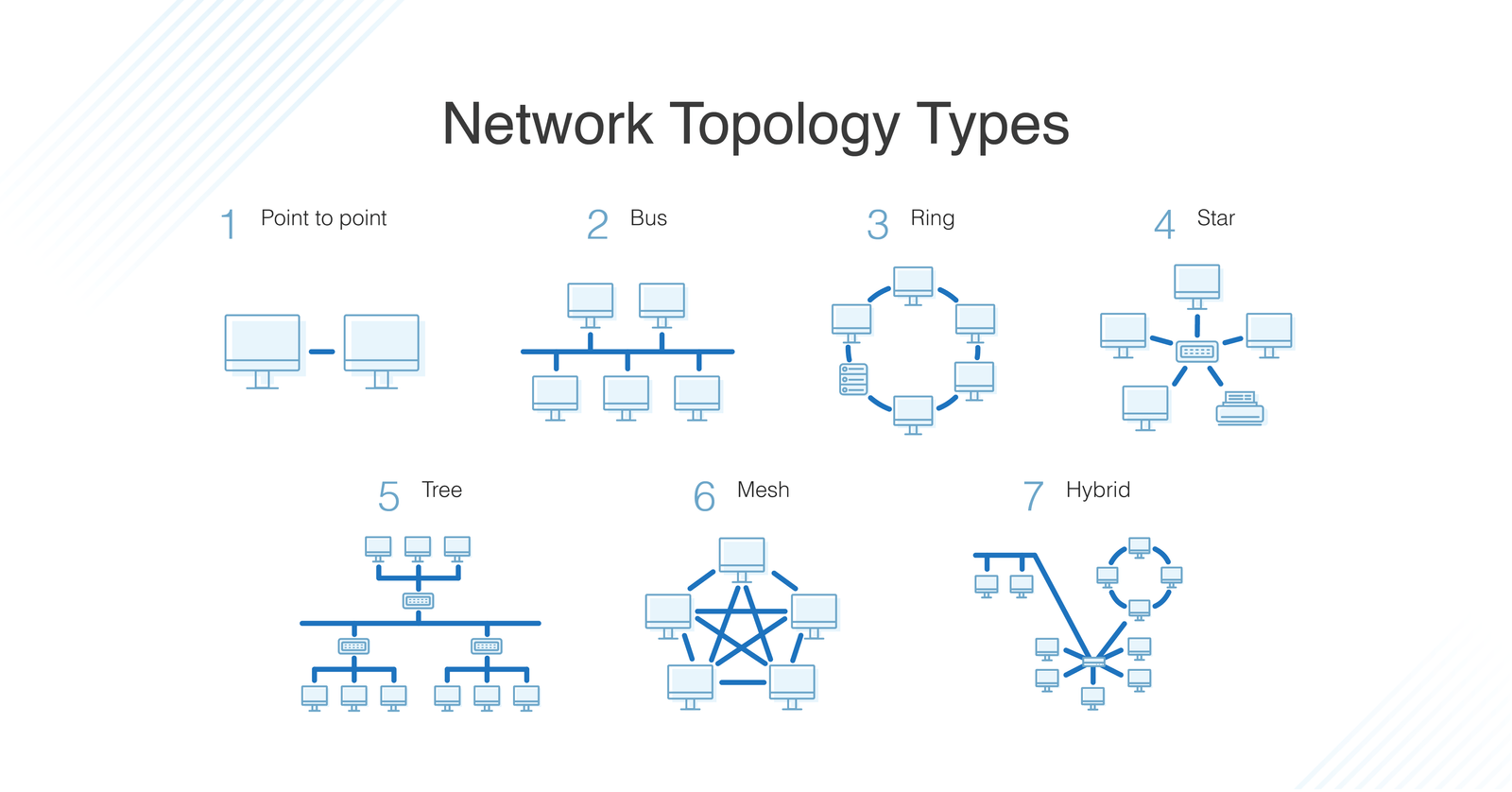
Network topology is the arrangement of connected devices and communication channels within a computer network. It defines how data flows between devices and can be physical (actual layout) or logical (data flow). Different topologies like bus, star, ring, mesh, tree, and hybrid offer varying performance, reliability, and scalability characteristics.

Types of Network Topology

  • Bus Topology
  • Star Topology
  • Ring Topology
  • Mesh Topology
  • Tree Topology
  • Hybrid Topology

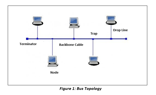
Bus Topology

In a bus topology, all devices are connected to a single cable called a “bus.” Data travels along the bus, and each device receives and processes the data, but only the intended recipient accepts it. Terminators are placed at both ends of the bus cable to prevent signal reflection and ensure proper transmission.

Advantages:

  • Easy to set up and understand.
  • Requires less cabling, making it cost-effective.
  • Suitable for small networks with few devices.

Disadvantages:

  • Susceptible to cable failures; if the main cable fails, the entire network can be affected.
  • Limited scalability; adding more devices can degrade performance.

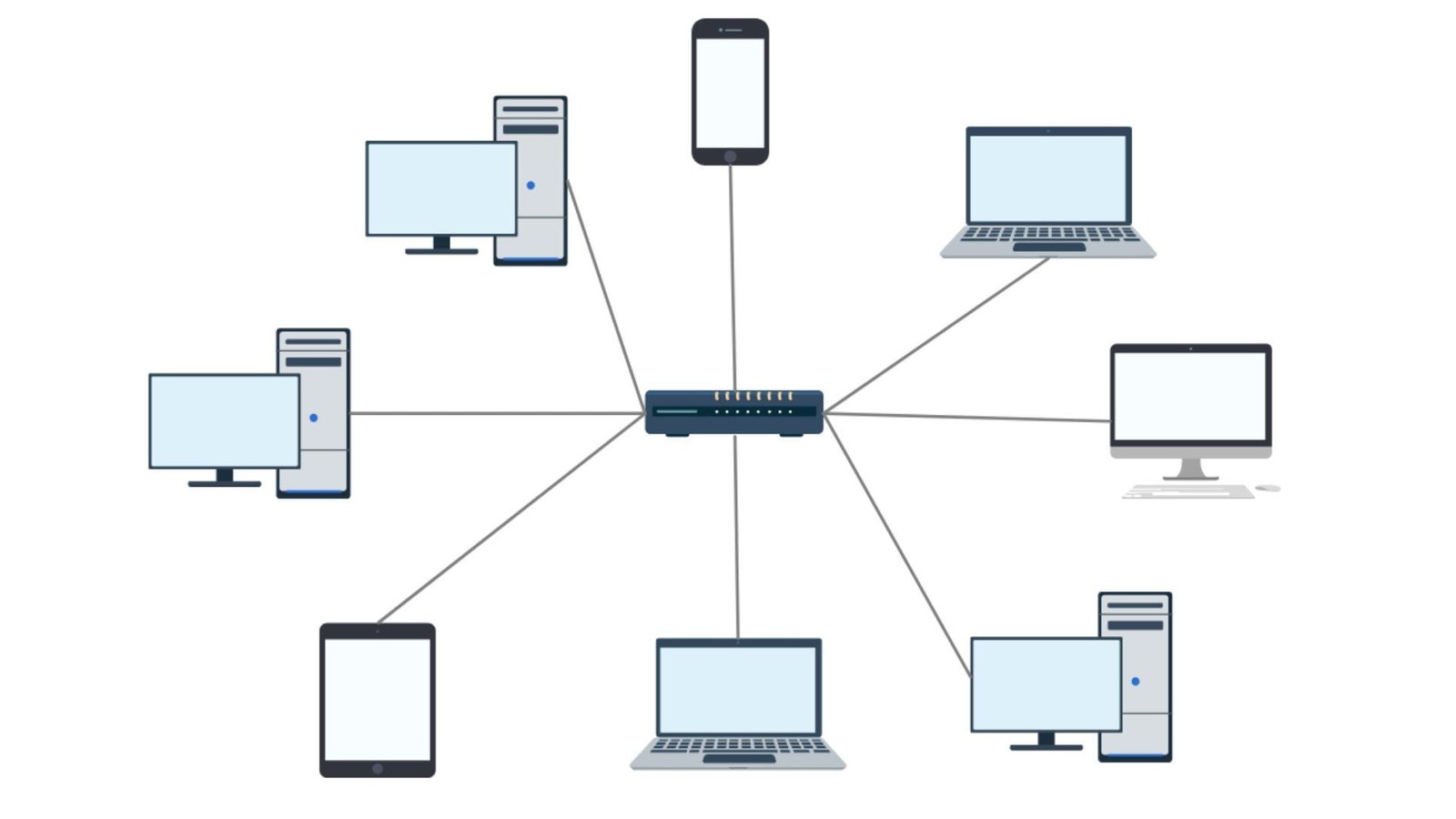
Star Topology

In a star topology, all devices are connected to a central device, such as a switch or hub. Data travels through the central device, which acts as a relay, distributing data to the appropriate devices. Each device has its own cable connection to the central device.

Advantages:

  • Centralized management and control.
  • Easy to troubleshoot; failures are isolated to individual devices.
  • Can handle high traffic loads without affecting other devices.

Disadvantages:

  • Dependency on the central device; if it fails, the entire network may go down.
  • Requires more cabling compared to bus topology, which can increase costs.

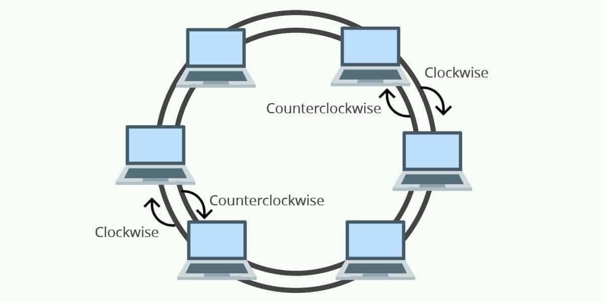
Ring Topology

In a ring topology, devices are connected in a closed loop, with each device connected to two neighboring devices. Data travels in one direction around the ring until it reaches its destination. Each device acts as a repeater, regenerating the signal before passing it to the next device.

Advantages:

  • Simple and easy to implement.
  • Data travels in one direction, reducing collisions and improving performance.
  • No central device required, reducing points of failure.

Disadvantages:

  • Susceptible to cable or device failures; if one device or cable fails, the entire network can be disrupted.
  • Difficult to reconfigure or add new devices without disrupting the entire network.

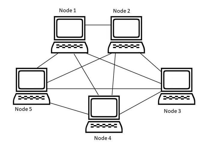
Mesh Topology

In a mesh topology, every device is connected to every other device in the network, creating multiple paths for data to travel. This redundancy provides high fault tolerance and ensures that data can still flow even if one or more connections fail. Mesh networks can be full mesh (every device connected to every other device) or partial mesh (only some devices connected to others).

Advantages:

  • High redundancy and fault tolerance; if one connection fails, data can still flow through alternative paths.
  • Scalable and able to handle high traffic loads.
  • Provides better security and privacy as data travels directly between devices.

Disadvantages:

  • Requires a large number of cables and ports, making it complex and expensive to set up.
  • Difficult to manage and troubleshoot due to the large number of connections.

Tree Topology

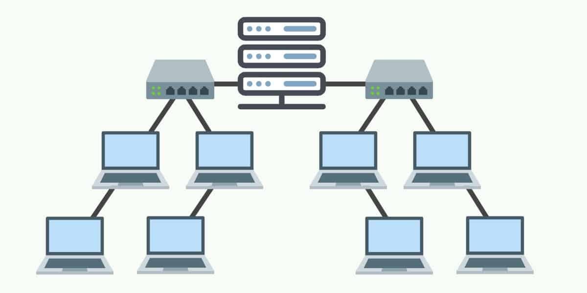
In a tree topology, devices are arranged hierarchically in multiple levels, resembling a tree structure. A root node at the top connects to multiple branch nodes, which in turn connect to leaf nodes at the bottom. Data travels from the root node down through the branches to the leaf nodes.

Advantages:

  • Scalable and provides a clear hierarchy for network management.
  • Can accommodate larger networks with multiple subnetworks.
  • Failure of devices in lower levels does not affect devices in higher levels.

Disadvantages:

  • Dependency on the root node; if it fails, the entire network can be affected.
  • Requires careful planning and design to prevent bottlenecks and ensure proper connectivity.

Hybrid Topology

A hybrid topology combines two or more different topologies to create a customized network design. For example, a network might use a combination of star and mesh topologies, or a combination of ring and bus topologies. Hybrid topologies offer flexibility and can be tailored to meet specific requirements and optimize performance.

Advantages:

  • Provides flexibility to meet specific requirements and optimize performance.
  • Offers a balance between cost, scalability, and fault tolerance.
  • Can leverage the advantages of different topologies while mitigating their disadvantages.

Disadvantages:

  • Complex to design and implement, requiring careful planning and integration.
  • Increased cost and potential for conflicts between different topology components.

Frequently Asked Questions

Q1: What is network topology?

Network topology refers to the arrangement of nodes, connections, and communication channels in a computer network. It defines how devices are connected and communicate with each other.

Q2: What are the common types of network topology?

The common types of network topology include:

  • Bus Topology
  • Star Topology
  • Ring Topology
  • Mesh Topology
  • Tree Topology

Q3: What is Bus Topology?

In Bus Topology, all devices are connected to a central cable, known as a bus. Data is transmitted along the bus, and each device receives the data but only processes information addressed to it.

Q4: What is Star Topology?

Star Topology features a central hub or switch to which all devices are connected. All data transmissions occur through the central hub, enhancing reliability and simplifying troubleshooting.

Q5: What is Ring Topology?

Ring Topology connects devices in a closed loop, where each device is connected to exactly two other devices, forming a ring. Data travels in one direction around the ring.